By: Akshata T.
Year: 2022
School: Aliso Niguel High School
Grade: 11
Science Teacher: Robert Jansen
This project is about building a simple light seeking solar powered robot. This will allow the robot to self charge and can have several applications. Some examples are self charging vacuum cleaners. The robot will save energy due to the solar power which is better for the environment. The robot will also save time while charging things because it can find its own energy source.
The circuit for the simple robot seeking light consists of a potentiometer and photoresistor combined to make a voltage divider. The photoresistor is used to detect light. When the photoresistor does not detect much light, the voltage divider outputs a low voltage. When the photoresistor is exposed to bright light, the voltage divider outputs a high voltage.
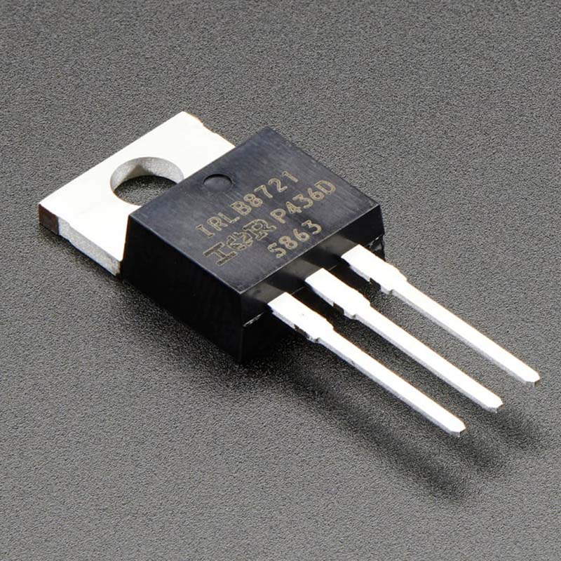
The MOSFET acts like a valve that controls the motor. When the input of the MOSFET receives a low voltage, the motor is off. When the input of the MOSFET receives a high voltage, the motor turns on and the robot moves towards the light source.
Electronic circuit requirements/criteria would be the following. The battery pack of four AA batteries provides a voltage of about 6 V to the circuit. The switch controls whether or not the battery pack’s positive terminal is connected to the circuit or whether the circuit is open or closed. The photoresistor and potentiometer form a voltage divider. The input to this voltage divider is the battery voltage (6V), and the output is V2. The potentiometer can be used to tune the voltage divider’s output. This allows adjusting to the robot’s sensitivity to ambient light levels. The output of the voltage divider is connected to the input (the gate) of the MOSFET. The source of the MOSFET is connected to the ground (0 V). So, for this circuit, VGS = V2. When V2 exceeds the threshold voltage Vth, the MOSFET will turn “on.” The motor is connected between the positive voltage supply and the MOSFET’s drain pin. When the MOSFET is “off”, the drain pin’s voltage is close to the battery voltage, so no current can flow through the motor. When the MOSFET is “on”, the drain pin’s voltage drops, allowing current to flow through the motor, into the MOSFET’s drain pin, then out of its source pin to the ground.